Compilable Segments was recently introduced to Labs as a quick way to segment out geometry and to get started with a compiled process very quickly. It's not a tool per se, but something we call an alias which is another way to help speed up a workflow by configuring a node or a set of nodes into a preset of sorts. In this tutorial, we will break down how the alias was made, but first...
What is an Alias?
First thing's first, what exactly is an alias in terms of Houdini? An alias is an alternate name given to a node with specific parameter presets set by default, or a set of nodes chained together in a specific way. For example, Tangent is an alias for the PolyFrame SOP with the parameters configured to calculate tangents in MikkT space.

Another example of an alias are the different For Each Blocks, which is configured with a For Each Begin wired into a For Each End with the settings configured differently depending on which type of block you chose. You can access aliases through the Tab menu as with all other Houdini nodes.
A Look at the Compilable Segments Alias
With the recently released Connectivity and Segmentation tool in Labs, we have also released a helpful alias for the tool called Compilable Segments, which is a quick setup for multithreading geometry processes. Connectivity and Segmentation was created specifically to make multithreading geometry easier, so we wanted to provide a quick way to get started with multithreading using Compile Blocks.
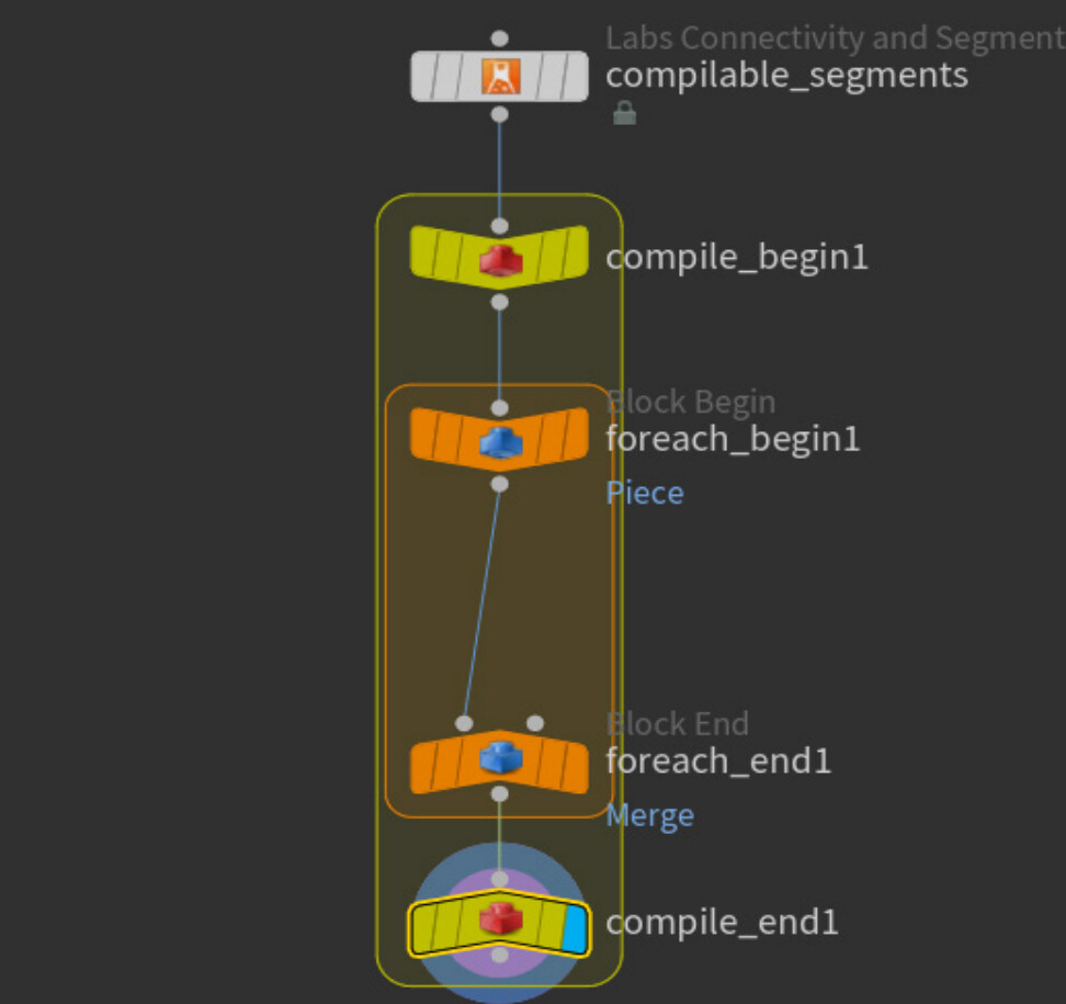
The alias drops down a Connectivity and Segmentation node with a For-Loop inside of a Compile Block with all the settings configured to multithread processes inside of the For-Loop, as shown below.
Role of Shelf Tools
An alias is essentially a hidden shelf tool. Remember, you can make a shelf tool automatically by dragging and dropping a sequence of nodes onto a shelf, and it will create a shelf tool that you can use again by either clicking the shelf tool or by using the Tab menu to drop down the shelf tool name.
You can access the Python code of the created tool by right clicking the shelf tool, left clicking on Edit Tool, then navigating to the Script tab to see the Python code. The code generated for an automatic tool may work well for certain cases, it is not very readable or easy to edit. Below is the script of an automatic shelf tool of a Sphere node wired into a Copy to Points node, and you can see how unreadable the script is:
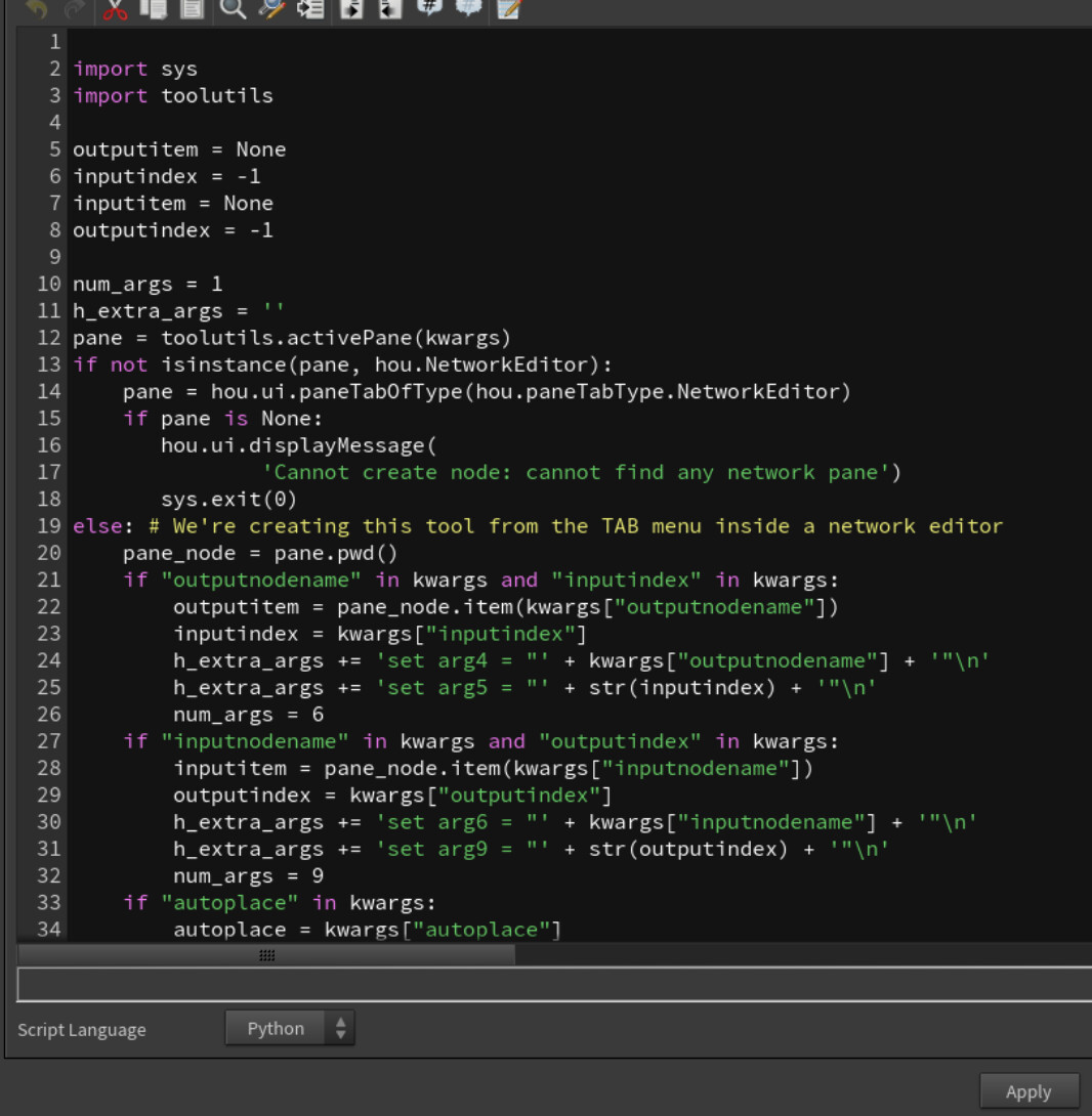
When the same exact tool can be made by writing a few lines of Python:

For Labs, we make aliases by manually scripting a shelf tool this way, or by directly modifying a .shelf tool that contains the tool. We save our aliases to the alias.shelf file if you are curious to see how we accomplish that.
Let's Make an Alias
Before we begin writing the code for an alias, we'll get the node layout assembled first, complete with custom-set parameters. The network layout for Compilable Segments is shown in the second image above. This tutorial is a detailed, step-by-step explanation for a moderately complicated alias with multiple nodes and multiple parameter adjustments. Simple aliases such as renaming nodes can be done by editing the .shelf file directly.
1. To get started on a new alias, right click on a shelf in Houdini and select New Tool.

2. From this window, you can set the Name, Label, and Icon of the tool. You can also choose which .shelf file to Save To. This window can be accessed again later by right clicking the shelf tool and left clicking on Edit Tool.

3. From there, navigate to the Context tab to set which context this alias will be used in. It will most likely be the SOP context.

4. Now we are ready to start scripting our alias. Navigate to the Script tab to begin. Here is the complete code for the Compilable Segments, and we will break down the different pieces of code further.
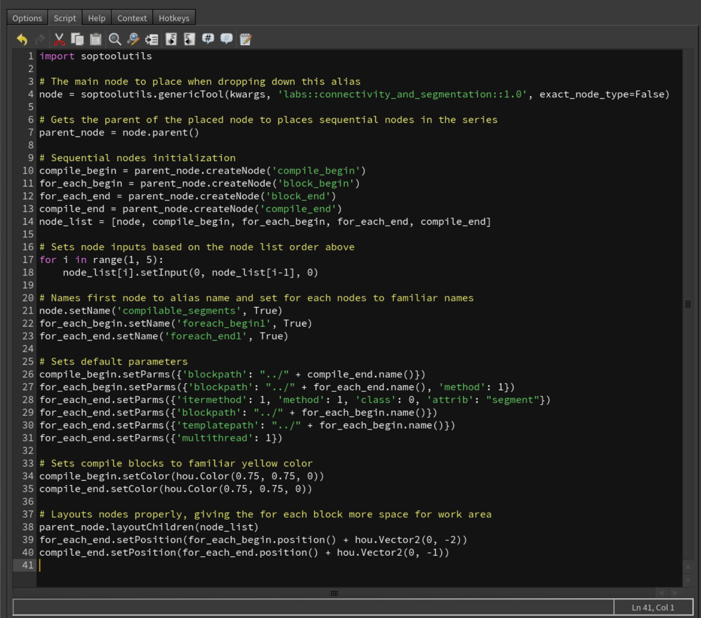
a. Node Initialization: In lines 1 - 14, we create all the nodes that we need, and we create a list to easily loop over them later on. Python functions used in Houdini are documented in SideFX’s documentation, but we will touch on a few specific functions.
The soptoolutils.genericTool() function allows you to place the tool from the Tab menu as expected, by moving your cursor in the viewport and clicking to set the tool down. This is done for the Connectivity and Segmentation node only, and the rest of the nodes needed for the network are created automatically in the parent node (current geometry node) afterwards with createNode().

An easy way to find the node label needed to call in these functions is by middle mouse clicking or opening the node info window to find the label. For instance, the Compile End label is compile_end.

b. Setting Inputs: The nodes are now created, but they have no relationship to each other yet. The list of nodes is populated in the specific order they should be connected in, so a for loop runs over the list starting from the second element (index 1) and sets the current node’s input to the previous node’s output with the setInput() function.

c. Renaming Nodes: We decided to rename a few of the nodes for several reasons. The alias uses our Connectivity and Segmentation node, but we wanted the name of the placed node to reflect the name of the alias, so the name was changed to “compilable_segments”. Also, when constructing a For-Loop from scratch, it starts with a Block Begin and ends with a Block End node, but we wanted the names to reflect the For-Loop structure that users are accustomed to seeing. These nodes had their names changed with the setName() function.

d. Setting Custom Parameters: Nodes are created with their default parameters, so they must be configured to work seamlessly together. With this example, Block Begin and Block End in the For-Loop must reference each others’ names with the blockpath parameters, and the Block Begin Compile node must reference the name of the Block End Compile node. We do this by getting the names of the necessary nodes with the name() function and setting the blockpath parameter values in lines 26, 27, 29, and 30 with the setParms() function.
Other parameters set include:
Line 27: setting the Method (method) parameter on the Block Begin node of the For-Loop to Fetch Input (value of 1)
Line 28: setting the Iteration Method (itermethod) to By Pieces or Points (value of 1), the Gather Method (method) to Merge Each Iteration (value of 1), the Piece Elements (class) to Primitives (value of 0), and the Piece Attribute (attrib) to segment to reference the segment primitive attribute output of Connectivity and Segmentation
Line 31: enabling the Multithread when Compiled toggle on the Block End of the For-Loop

e. Finishing Touches: To keep the visual elements of the workflow familiar, we colored the Compile Blocks their distinct yellow color using the setColor() function. Secondly, the nodes that are created at the origin in the Network view unless otherwise specified, so the layoutChildren() function was used on our node list to evenly align them from our initially placed node. We moved the two End Blocks down a bit further to create a space between the For-Loop blocks to make it easier for users to start inserting their own nodes into the workflow.

5. (Optional). One last step is transferring aliases manually between .shelf files. If you navigate to the .shelf file the toolbar is saved to, you will see that the the tool’s code exists within. This will usually be the default.shelf file, but you can create multiple .shelf files to use. Below is a screenshot of part of the code as seen in the alias.shelf file.
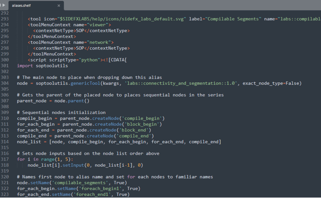
You can copy the code starting from and ending with and paste this within another .shelf file.
Note: if you want to take a tool off of a toolbar, only do so with the Remove from Shelf option. If you select the delete option, it will delete the code within the .shelf file. Keeping your aliases within a separate .shelf file will prevent accidentally deleting an alias. An alias or tool that is removed can still be accessed with the Tab menu or added again to a shelf, but an alias that is deleted is gone.

—
Danicka Oglesby
Houdini Technical Artist, SideFX Labs